
 中文
中文
Abstract:
The paper introduces the successful application of SUNFAR V360 Vector Inverter on power supply frame.
Keywords: Inverter; V360; Motorized pay-off; PID
Introduction
The cable industry tends to develop with higher technical level, where the products are diversified, and the production is automated. In this industry, supply frame is used most widely at present, while power supply frame is the device with higher technology. It is commonly required that the inverter for power supply frame should have PID adjusting function, and PID should be two-way control. In the present industrial application, SUNFAR V360 Vector Inverter can meet the control requirement without any assistant components. Combining the self-contained PID controller of SUNFAR V360 Inverter, the article introduces the motorized pay-off system controlled by constant tension, which is designed for cable industry.
Introduction of process of motorized supply frame
Power supply frame, as the most forward part of many devices, is used widely in the cable industry. In general, requirements of the power supply frame are as follows:
- When the guiding speeds up, the pay-off should speed up rapidly accordingly;
- When the guiding speeds down, the pay-off should speed down rapidly accordingly;
- When running stably at a speed, the swing bar of the supply frame should be stable.
- When loose line or disconnection occurs, it is required that the pay-off plate should be able to make reverse rotation automatically.
All the above requirements are achieved by PID function of the inverter, and the inverter should make sensitive response to the speed. In the light of the above requirements, V360 inverter is employed to design the control system as follows:
Control program
As is shown in Diagram1, the simultaneous control of the constant tension of the pay-off is achieved by the following steps. The position change of the tension swing bar in the system outputs voltage signal to feed the PID control system of the inverter. Through the automatic calculation of PID controller, the inverter change the output frequency, thus adjust the running speed of the pay-off motor, so as to maintain the constant tension. In fact, this is an indirect way of tension control. The fine tuning of PID is calculated based on the actual position of the swing bar, not direct tension calculation, and there is functional relation between the position and the tension, so the tension control can be achieved by controlling the actual position of the swing bar.
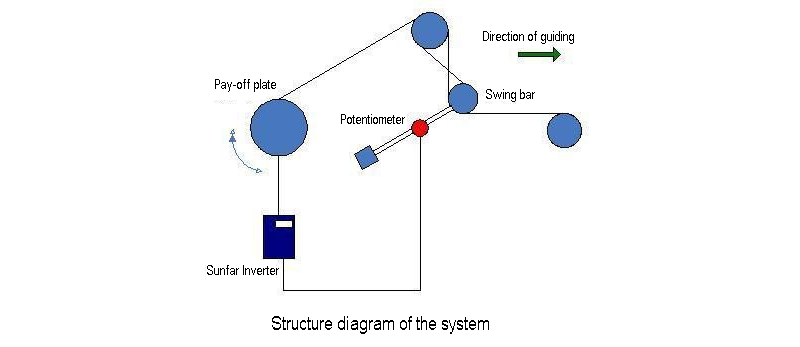
Figure 1
Block diagram of system principle, wiring diagram and introduction of control principle
Block diagram of system principle is shown in Figure 2:
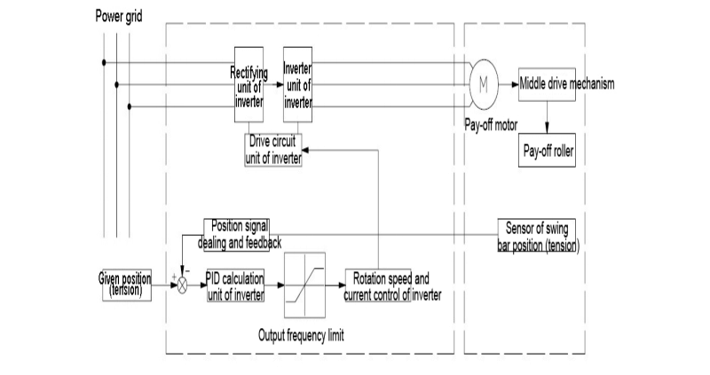
Figure 2
Wiring diagram of the system is shown in Figure 3:
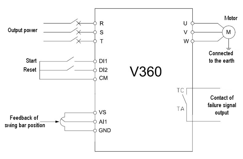
Figure 3
The system employs pattern of open-loop vector, where analog input AI1 connects feedback signal (0-10V) of the swing bar position, and set the desired position of the swing bar as the given value of PID. During the operation process, the system keep comparing the feedback signal and the given value, according to which PID controller makes automatic calculation, changes the output frequency, adjusts the rotation speed of the pay-off motor, and ensures the stable position of the swing bar, so as to achieve the control of the constant tension.
Parameters settings of inverter:
|
Function code |
Name |
Default value |
Set value |
|
F0.0.09 |
Motor type and control mode selection |
0000 |
0000 |
|
F0.1.16 |
Selection of frequency set value |
0 |
2 |
|
F0.1.22 |
Lower limit frequency |
0.0 |
2.0 |
|
F0.2.25 |
Frequency setting channel 1 |
2 |
23 |
|
F0.2.26 |
Frequency setting channel 2 |
0 |
23 |
|
F0.2.31 |
Maximum frequency setting 2 |
50.0 |
20.0 |
|
F0.3.33 |
Control command 1 |
0 |
1 |
|
F1.0.03 |
Acceleration time1 |
5.0 |
1.5 |
|
F1.0.04 |
Deceleration time 1 |
5.0 |
1.5 |
|
F5.3.28 |
PRI selection of frequency (rotation speed) command source |
0000 |
0007 |
|
F7.0.00 |
Process PID function selection |
0000 |
0001 |
|
F7.0.08 |
External given number of the process PID |
0.0 |
50.0 |
|
F7.0.13 |
Analog feedback corresponding to 100% feedback |
5.00 |
10.00 |
|
F7.0.17 |
Proportional gain |
2.0 |
0.8 |
|
F7.0.18 |
Integration time |
20.0 |
2.0 |
|
F7.0.21 |
Characteristics configuration of PID controller |
0000 |
0010 |
|
F7.0.22 |
Allowed static deviation |
5.0 |
2.0 |
|
FF.0.00 |
Lock function of FF configuration parameter |
0000 |
0001 |
|
FF.0.01 |
Definition of virtual output node (SDO1) |
0 |
7 |
|
FF.0.09 |
Definition of virtual input function (SDI1) |
0 |
12 |
Conclusion
This paper introduces the control system of motorized pay-off of constant tension based on the SUNFAR V360 Vector Inverter. The program has sensitive response to speed, can meet the technical indexes of the device on the sides of both high-speed tracking and reverse winding of loose line, and can also make separate limit on the forward pay-off speed and the reverse winding speed, with consideration of the pay-off speed requirement and the winding speed protection. It has been applied successfully to several motorized pay-off system at present.
References:
Specifications of V360 Series High Performance Vector Inverters, Shenzhen SUNFAR Electric Technologies Co., Ltd.
Post time: Sep-14-2018