
 中文
中文
Based on the E380A general-purpose inverter, SIMPHOENIX Electric had developed a special machine for spinning in terms of its operation process in textile mill. It’s used for controlling the drive system of the double-speed motor in the original spinning machine to achieve high production efficiency, low yarn end breakage rate and less operating strength for workers. Meantime, on the basis of the standard MODBUS RTU protocol built in the SIMPHOENIX inverter, it uses Delta text TP04G as the inverter’s human-computer platform, which is convenient for modifying and monitoring relevant parameters of the machine.
- Background of the innovation in the spinning machine
The innovation in this spinning machine lies in the reform of frequency control of the main motor—a kind of AC double-speed motor that has six poles in low speed and four poles in high speed, generally having power of 18.5 KW or 22 KW. The low speed is functioned during the time of mechanical equipment maintenance and the machine starting period, while it will change to high speed after normal running. As a result, the power frequency of the spinning machine after normal running will keep in 50HZ no matter in large, medium or small yarn section, which also leads to high yarn end breakage rate. However, by adopting the reform of the frequency control, it can artificially adjust the running speed of each yarn section by reducing the frequency in large and small yarn sections at high breaks rate and increasing the frequency in the medium section at low breaks rate. Meanwhile, as the length of the medium yarn section is accounted for the overwhelming majority of the whole yarn length, using this way not only can improve the production efficiency, but also can reduce the breakage rate.
- Electrical Transmission of the Main Motor in Original Spinning Machine
The operations of the original spinning machine are mostly centralized on the head parts such as low-speed start button, high-speed button, stop button and ring bar reset. The electrical circuit and components are distributed in the end control box mainly including low and high speed contactors and other intermediate relays. The low speed function will not work after starting high speed mode, and it needs to restart it after a manual shutdown.
On the original spinning machines, there is an automatic doffing signal that can output a pulse signal from a relay after finishing the doffing and stop the motor, called as mechanically automatic doffing. The signal is controlled by parts of double-cam mechanical structure and electromagnet. When the doffing is finished, one cam will press a switch and output a contact signal from the relay, and this signal induces the electromagnet to get the electricity and attract an armature to make the other cam move. Then the previous cam reset, so do the relay and the ring bar, which is called as three automatic actions. If the machine is shut down manually, it requires to manually reset the ring bar and cam mechanism. Some simple spinning machines without mechanical automatic doffing function need manual stop. That is to say, the machine will be shut down by hands when the operator sees the yarn is almost finished. It’s very important for such a machine to cyclical finish outputting the signal by the inverter. With this signal, the machine can be reformed with automatic doffing function, which only requires pressing high speed start button after each doffing and yarn changing.
1. Control method after frequency transformation
In the condition of reducing wiring changes and retaining original operational method as much as possible, it only needs slight modification to the electric circuit. The frequency conversion controls circuit shown as follows:
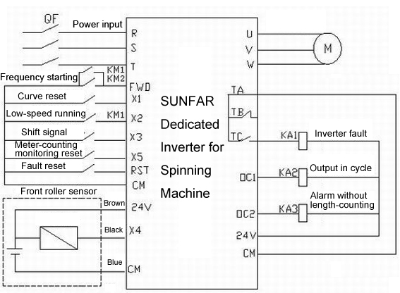
The original low-speed function of the inverter only plays a role during overhaul or testing period. After the confirmation of the machine in normal, the high speed mode will be activated directly as the inverter itself works very smooth and runs with variable-speed curve according to the setting process. It should be noted that as the high speed mode is started directly after low speed while the motor is still in running, the over current will be easily alerted if the inverter is directly started. As a result, the start function of speed inspection cannot substantially take into effect. Therefore, the low speed function is not suggested if it’s not in the test running or in overhaul period.
As the inverter has a curve cycle to finish outputting the pulse signal, the main high-speed contactor will cut off. Then the running signal of the inverter cut off, and the automatic electric doffing is finished. Next time, it only needs to start the high speed function directly.
As for the original spinning machine with mechanical automatic doffing function already, it needs to pay attention that the electric doffing length should be set longer than original mechanical automatic doffing length, so that each segment can be reset automatically before finishing the doffing. Moreover, it can start the pulse missing treatment by parameters when the sensor is in failure. Because the inverter will output the alerting signal without length counting and set the frequency by digital characters, the frequency should be set to zero, and then it can automatically start from the breakpoint after fault recovery.
2. The processing curve and the inverter parameter settings of spinning machine
a. The processing curve is shown as follows:
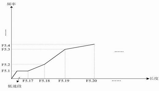
Low-speed section
b. Relevant parameters of curve setting
F5.1-F5.15 Set frequency 1 in multiple sections of speed - frequency 15 in multiple sections of speed
F5.16 Set low speed running frequency
F5.17-F5.30 14 Set run length 1 – run length
F5.32 Set doffing length (the running frequency of doffing is decided by parameter F5.15)
3. Explanation of the processing curve
(1). In the initial period, the command of low-speed running of the inverter is in effect, and the inverter outputs the command of low speed running.
(2) After withdrawing the low-speed operational command, the inverter runs in the light of the curve setting in the multiple sections of speeds. The inverter accelerates to multi- speed frequency 1. The frequency gradually increases along with the increasing of the length in first section. After finishing the first length, the inverter runs with multi- speed frequency 2 and the whole process changes in constant speed.
(3) The doffing length in the each section will be increasingly set in turn. Therefore, the parameter can start from the full length of the yarn in setting stage and then gradually reduce the length setting of each segment. The length of each segment should be limited to the parameter in the next section, satisfying the following relations: 1st length < 2nd length < 3rd length…….. < 13th length < 14th length.
(4) Setting requirements should be according to general experience:
a. The small yarn section is accounted for 15% of the whole length while the end breaks rate is accounted for 70%. Therefore, it can properly reduce its output frequency according to the yarn conditions to decrease the breaks rate.
b. The medium yarn section is accounted for 80% of the whole length and has low breakage rate which is only accounted for 10%. Thus it can properly increase the motor speed in this period to enhance the efficiency.
c. The large yarn section is accounted for 5% of the whole length and its breakage rate is accounted for 20%. Thus it can properly reduce the motor speed in this period to improve the product quality.
F3.0=20,F3.1=21,F3.2=22,F3.3=23,F3.4=24,F3.8=16,F3.6=9,F3.7=10,F5.0=1011,
F0.4=0001,F9.0=0114.
The above parameters are set by the text display TP04G and then can be modified in real-time communication with the inverter.
4. Cooling method of the inverter
As the special inverter for spinning machine is designed without cooling fans, it needs to make use of airflow in itself to cool the inverter. At present, the method adopted by most factories in practice is using blower to send the cold air through the trench from outside to each main motor in the end of the machine for cooling. And the hot air will be expelled through the airway tube out of the workshop. Thus an airway tube can be used to lead the air from the place of the air intake of the motor into the inverter radiator, and then the hot air will be discharged to the workshop. After observation, the temperature of the inverter in long running is between 55 to 60 degrees.
Reference:
SIMPHOENIX E380 Operation Manual
Operation Manual of SIMPHOENIX Dedicated Inverter for Spinning Machine
Post time: Sep-17-2018