
 中文
中文
Abstract:
The traditional bridge crane, with high energy-consuming electronic control system, high failure rate and poor speed governing precision, is no longer able to satisfy the requirements of modern industry. Applying frequency control technology in bridge crane system could effectively improve reliability and speed governing precision and yield a certain energy saving effect.
Keywords: Inverter; Bridge crane; Wound rotor motor
1. Introduction
Bridge crane is handling equipment widely used among industrial and mining enterprises. In the traditional relay-electric contactor control system, the contacts of contactors often burn out because of the inrush current from motor, which is due to the poor working conditions of bridge crane, often under frequent starting, braking, reversing, variable speed and heavy load, added with large inrush current and vibration. It results in constant maintenance, high maintenance costs, inestimable loss caused by the shutdown of production line. Moreover, the traditional crane governing system integrated with worse comprehensive technical indicators could not meet the requirements of industrial production. Meanwhile, AC VVVF system, featured by high speed-governing performance, reliable operation and convenient maintenance, provides a wholly new solution for the control of bridge crane. This solution is characterized by simple control line, stable operation, little maintenance and a perfect, protection monitoring function .It is highly efficient and energy saving . Therefore, the adoption of AC VVVF becomes the mainstream of AC speed regulating technology.
2. Structure and control of bridge crane
The bridge crane is a device across fixed space, used to lift various objects. It is generally consisted of four parts, lifting car, bridge metal structure, bridge travel mechanism and electric control equipment. Travel mechanism mainly refers to the main lifting mechanism, vice hoisting mechanism, trolley travel mechanism and cart travel mechanism. In the electrical control system, the power is generally conveyed by the conductive device of trolley (auxiliary slip line) and the total power conductive device of crane (main slip line) to the central appliance.
Bridge crane could realize vertical, horizontal, longitudinal motion of heavy objects in three-dimensional space, which is driven by the motor of carts and the objects moves back and forth along the two sides of the track. Trolley and lifting mechanism are driven by the motor of trolley, and move left and right along the track of the bridge. When lifting heavy objects, it moves up and down driven by crane motor, as shown in Figure 1.
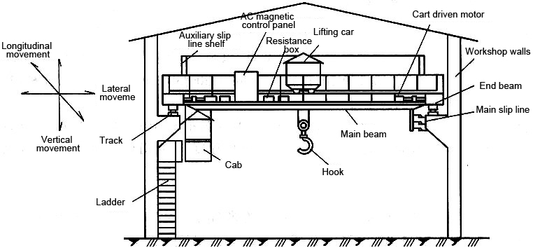
Figure 1 The main structure and moving style of bridge crane
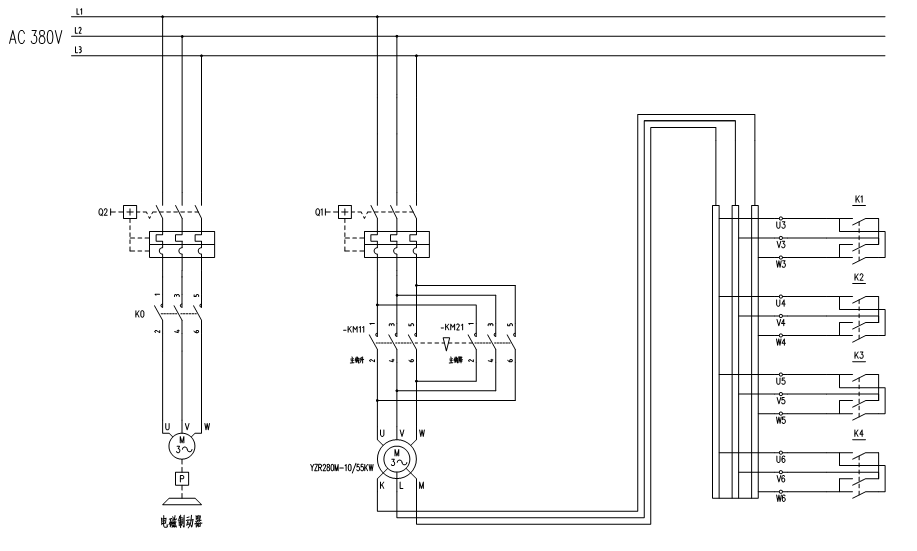
The traditional bridge crane generally uses the relay-contractor control system and AC wound motor .It starts to work and the speed is regulated through rotor resistance, as shown in Figure 2. When beginning to work, rise contactor or drop contactor pulls, electromagnetic brake contactor opens the brake, the contactor on the speed regulating resistor stops working and motor operates at a low speed. When the speed needs to be changed, the resistance value of the rotor coil could be changed by pulling various contactors on the speed regulating resistor so as to alter the revolving speed of motor. Such control system has many shortcomings, and the motor rotor resistance governor is an energy-based governor with high energy consumption, soft mechanical properties, small speed range and bad smoothness. Under the circumstance of frequent switching relay –contact control system, the surge current is large, contact burns and smokes comes out from brush. It happens quite often that the motor and rotor resistance burn out and crack.
3. Characteristics of VVVF system
With the development of power electronics technology, the performance and stability of inverter have been greatly improved, thus the use of inverter on crane becomes possible, which fundamentally removes the shortcomings of electronic control system of traditional bridge crane . When applying frequency control in lifting equipment, the requirements of each travel mechanism of crane for transmission system must be understood first.
(1) The crane should have a big starting torque, which is usually more than 150% of the rated torque. When taking factors such as overloading experiments into consideration, at least 200% of the rated torque should be provided during the starting and accelerating process.
(2)Due to the existence of mechanical brake and in order to realize smooth switching between the output torque of the inverter and the braking torque of the mechanical brake without producing the glide-hook phenomenon, the control timing of the start signal of inverter and the actuation signal of mechanical brake must be adequately discussed.
(3) When the hoisting mechanism runs down or the translation mechanism rapidly decelerates, the motor will be in a state of renewable power generation, its energy will be fed back to the power supply side. The discussion on how to deal with this part of the renewable energy should be carried out on the basis of the situation at the scene.
(4) The load changes rapidly when the hoisting mechanism grasps heavy objects off ground or the objects contact with the ground .The inverter should be able to smoothly control the impact load.
According to the above operating features of the crane, the main equipment of frequency control system will be selected according to the following methods:
3.1 Selection of inverter capacity
3.1.1 The capacity P0 (kVA) of drive inverter on hoisting mechanism (main/auxiliary hook) must be greater than the demand of load:
P0≥k×Pm/(η×cosφ) (1)
Where k refers to overload factor, the multiple of the biggest output torque and specified torque of motor (usually 2) divided by the overload factor of inverter;
Pm means the output power of the motor shaft demanded by load (kW);
η is the motor efficiency (usually about 0.85);
cosφ is the motor power factor (usually about 0.75);
P0≥k×Pm/(η×cosφ) (1)
3.1.2 Translation mechanism includes gyratory mechanism of carts and trolley. More than one motor is used for transmission in most cases. Thus drive inverter employs the form named as “one dragging more”. The capacity of the drive must be greater than the total current demanded by load:
ICN≥k×n×In (2)
Where k refers to the correction coefficient of current waveform, which is from 1.05 to 1.1 when PWM modulates.
In is the rated output current of one motor under power frequency (A);
ICN is the rated output current of inverter (A);
n means the number of inverter-driven motor;
ICN≥k×n×In (2)
3.2 Selection of braking unit and braking resistance
3.2.1 Selection of braking unit and braking resistance on translation mechanism
The braking unit and braking resistor on the drive of translation mechanism is usually selected according to the standard configuration of the inverter, braking unit and braking resistance on the inverter instruction book.
3.2.2 Selection of braking unit, braking resistance on hoisting mechanism
During the declining process, the hoisting mechanism has great renewable electric energy and it will last for a long time. Braking unit and braking resistance need to be reconfigured to ensure the normal work of the inverter.
(1) Calculation of resistance value RB
The minimum resistance value Rmin of RB is determined by the maximum current value I (max) of the inverter and the technical specifications of brake unit are shown as follows:
Rmin= VC /I(max) (3)
In order to meet the requirements of the braking torque, the maximum resistance value Rmax is obtained by the maximum braking power PB (max):
Rmax=V2C / PB(max)= V2C /(130%×Pe) (4)
The range of resistance:
Rmin<RB<Rmax (5)
Where VC is generally 700V
Pe is the rated power of motor
(2) Rated power of resistance PR
PR>0.8 Pe/m (6)
Where m refers to the increasing rate of power of resistance, it could be found by manual selection of resistance and generally calculated by 1.5.
Rmin= VC /I(max) (3)
Rmax=V2C / PB(max)= V2C /(130%×Pe) (4)
Rmin<RB<Rmax (5)
PR>0.8 Pe/m (6)
4. Design of crane frequency control system
4.1 Electrical design of frequency control system
Take frequency transformation of hoisting mechanism of 50T double-beam bridge crane in a transformer factory in Liyang, Jiangsu for example. The details of the design of crane VVVF are given as follows. This crane hoisting-mechanism-driven motor uses YZR315S-10 motor, the power of which is 55KW. According to the formula (1) and the motor parameters, the calculation result is that the capacity of inverter required by hoisting mechanism is 93KVA. Now using the high-performance heavy-load vector inverter A510-4T0750 produced by Si Fang Electric Group, the capacity changes into 98KVA. This inverter has a super overload capacity and starting torque as well as a variety of typical macro parameters that could be a complete set. The built-in three-phase filters and reactors reduce harmonics, enhance anti-interference capacity, thus it is ideal for the application of crane hoisting mechanism in working conditions. Braking resistance could be obtained according to equation from (3) to (6). The concrete design is shown in Fighre3. Because it is unnecessary to connect resistors to modulate speed, short circuit should be employed for the rotors of motor.K1 and K2 are positive rotating and negative rotating signal.K3, K4, K5 are multi-speed control signal. Electromagnetic brake contact controls the brake action of electromagnetic.
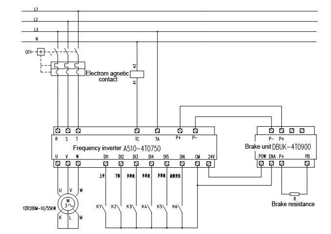
Figure 3 Electrical design of VVVF hoisting mechanism
4.2 Control points of VVVF system of crane
In the bridge crane control system, carts and trolleys are generally consisted of one inverter with multiple motors. Thus inverter employs U/F control mode, while the hoisting mechanism uses one-to-one control mode and non-inductive vector control mode is employed so as to acquire good performance. The moment before the crane electromagnetic brake hugs and after it releases the heavy objects, these objects are prone to decline from the original stopped state and slide the hook. Main consideration on this issue refers to the pull-in time of inverter and electromagnetic brake contactor. When the brake opens earlier during the lifting and declining process, glide-hook phenomenon will easily appear. But if it opens later, inverter are particularly prone to brake down. During the declining process, if brake happens earlier, inverter tends to brake down. If brake comes later, glide-hook phenomenon will appear. Thus, there are two key points to solve the problem.
1) Control points of stopping the lifted heavy objects
Set the starting frequency and maintaining time (should be greater than the Holding time of brake magnet, 0.6S). When the operating frequency of the inverter falls to a certain level, the inverter outputs” frequency arrival signal” and sends out the outage signal to the brake electromagnet, which will last for a while and then the operating frequency will fall to 0 HZ.
2) Control points of rising and declining the lifted heavy objects
Set the lifting and falling starting frequency and detect current time. When frequency arrives, frequency begins to detect current at the same time. The current should be large enough and the moment could offset the opening instruction sent out by torque, which will force electromagnet to be connected with electricity and release the brake. It should be greater than the span of the time when electromagnet releases the brake, added with coordination between other parameters and machinery. For example, the accelerating and decelerating time of inverter and the degree of tightness of spring of electromagnet brake. The specific control logic is shown in Figure.
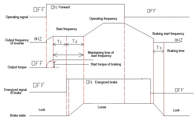
Figure 4 Control logic of electrical mechanical brake
Conclusion
Compared with the original system by using a large number of that plant on-site equipment,it has high precision in speed regulation, runs smoothly, accelerates the speed of assembly and improves work efficiency. The starting torque is large at low speeds and the system starts smoothly, which not only reduces mechanical impact on the reduction box, couplings, wire rope, but also lowers impact on the grid, largely decreases maintenance costs, yields remarkable energy-saving effects and fully verifies the validity and feasibility of this program.
References
[1] Practical Electrical and Technical Manual for crane Fu Deyuan, 2011
[2] Li Fangyuan. Application and Practice in Inverter Industry, 2006 (1)
[3] A510 instruction manual Shenzhen Simphoenix Electric Technologies Co., Ltd., 2012 (V1.1)
Post time: Sep-17-2018