
 中文
中文
Abstract:
This paper describes the structure and control requirements of the construction hoist, and makes a detailed description of electrical design, model selection, safety testing and adjustment methods of VVVF system of construction hoist.
Keywords: Inverter; Construction hoist
1. Introduction
With the development of construction industry of our country, and the continuous improvement of mechanization of construction, the requirements for the manufacturing quality of construction hoist and technological level of the machine are increasingly higher. The ordinary lifts generally use contactor – relay control mode, direct start, and the mechanical brake forcing brake. The impact is huge when starting or braking the lift, which could also severely damage mechanical structure and organization, destroy electrical components and easily result in material inside the lifts falling off. It not only affects the efficiency of the construction but also the economic returns of the construction enterprise. Especially in the dual-use construction hoist for people and goods, there is a great security risk. With users’ increasing demands for the performance and safety of construction hoist, the traditional control mode has been more and more powerless.
Due to the above-mentioned reasons, professional manufacturers at home and abroad have tried more new accelerated applications, such as employing variable voltage control system of multi-level motor, bringing in VVVF and so on. With the continuous development of frequency conversion technology, it betters any other governor program with its absolute advantages and takes the leadership. Lifts with VVVF is featured with many merits, such as the zero speed brake without damaging the braking, perching at any low speed and high leveling accuracy. The smooth transition of speed has no impact on the organization and structural components and improves the safety of the lifts. The speed range could be arbitrarily adjusted, which improves the work efficiency of the lift. Besides, the energy-conserving speed controlling pattern could reduce energy consumption of the running system. Due to these evident characteristics and advantages, the inverter is widely used in the lifts. It is of great significance to the safe operation of the lift and the reduction of energy consumption.
- 2. Structure and control of the lift
The construction hoist is a kind of construction machinery which carries person or cargo by using a suspension coop (or platform, hopper) along the guiding track or rails up and down. It is widely used in construction and other fields, such as industry, civil construction, bridge construction, underground construction, large chimney construction and other workplace, where it is used to transport materials and it also becomes an ideal equipment of the personnel. As a permanent or semi-permanent construction hoist, it could also be used in warehouse and towers. Besides, as the busiest machine for vertical transportation in the construction of high-rise buildings, it has been generally accepted as one of the key indispensable equipments.
The main components of the construction hoist are guiding track, suspension coop, drive system, coherent-wall shelf, chassis guardrail, system, safety devices, cables and power supply unit as Figure 1 shows.
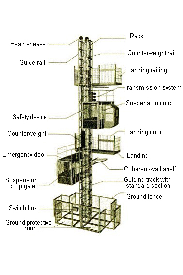
Figure 1 Structure of construction hoist
3. Design of VVVF system of the lift
3.1 Introduction of the structure of VVVF system
The VVVF system of the lift is consisted of the following sections: disc-brake three-phase asynchronous motors, variable-frequency governor, inverter braking unit, braking resistor, linkage units and electrical protection device. The control process is implemented as follows: Operate on the speed-transfer switch on the linkage unit and select speed gear and then output signal to the inverter to change the frequency so as to realize speed regulation.
3.2 Key points of designing electrical system
3.2.1 Selection of motors
When the basic parameters of the drive system (such as maximum lifting weight, maximum operating speed, etc.) are given, the series and the power of motor can be determined and calculated. The hoisting mechanism of the construction hoist should use variable frequency motor that is suitable for frequent starting and has small moment of inertia, and large starting torque. The power of the motor should be selected based on the size of the drive mechanical load.Its formula is:
P=WV/(η×10-3) (1)
Where: W is defined as the sum of rated load gravity, suspension coop and the gravity of the ropes.
V is the running speed, m/s;
η refers to the mechanical efficiency (the product of transmission efficiency of each section of transmission part).
The motor and the inverter are required to operate at low speed because the load torque of the lift is a constant torque and basically unchanged. Thus the power of the motor needs increasing or an external fan should be added for cooling.
3.2.2 Selection of inverter
After the motor used for the system is ascertained, the design of the control system could begin. The first step is to select a type of inverter. Nowadays there are many inverter brands at home and abroad with vast difference in control level and reliability. The inverter featured with vector control or direct torque control, stable operation and high reliability are the first choices for transmission mechanism of the lift. Due to the difference of the inverter brands, even in the same power, the overload capacity and the rated current of inverters could be different. Therefore, when choosing inverter capacity, not only the size of the speed should be noticed, but whether the rated current is greater than that of motor needs to be checked. The capacity of the inverter is generally one category larger than motor. Take the inverter produced by Si Fang Electric Group for example, in the SC100 series construction hoist, the power of each motor is 1 KW thus the total power of motors is 2×11=22kW. The V360 series inverter with reliability and high performance produced by Si Fang Group is a good choice.
3.2.3 Selection of braking resistance
As used for lifting, the designing point of the frequency conversion system lies in the reliability of the system itself when the motor is in the feedback braking state, as the failure of such system often occurs in the working condition when suspension coop descends, such as over-voltage, over-speed, car slipping and so on. During the declining process of the frequency conversion system, the motor is in the power generation state. Renewable energy returns to the DC bus of the inverter. DC side access is usually used for energy-consuming devices such as braking unit, braking resistor and so on.
Here map can represent the status of diverse parameters in the lift frequency conversion system.
When declining at an even speed, the power in steady state consumed by resistor is:
Pe=ωmMeδ (2)
During the decelerating process, the consumption of peak value is
Pm=Pe+δJ (ωm-ωd)/Ta (3)
Where ωm means the declining speed before deceleration .
ωd is the declining speed after deceleration .
Me is the load torque
δis the reverse efficiency in the transmission system
J is the moment of inertia in the transmission system
Ta is the deceleration time
To determine the exact value of these parameters, it is of certain difficulty in the initial designing period of the system. Before the completion of the products, the transmission inertia of various components cannot be accurately measured and calculated. In actual use, the deceleration characteristic of the system changes in accordance with the needs of the scene. Therefore, in most cases, the value is generally between 40% and 70% of the motor power. The calculation of resistance value R of braking resistor is selected according to the following range.
Rmin≤R≤Vc2/0.8P (4)
Rmi≤Vc/Ic (5)
Where Vc refers to the operation voltage of brake unit,
Ic means the maximum allowable current of brake unit
P is the rated power of motor
3.2.4 Design of control circuit
The following design flow is the concrete directions of control circuit of inverters produced by Si Fang Group in construction hoist. The electrical system of the lift is mainly consisted of main circuit and control circuit. The electrical schematic diagram is shown as figure 2.The electrical schematic diagram of the control circuit is shown in Figure 3.The electrical transmission part consists of two sets of asynchronous motor which are controlled by one set of V360 series inverter. The rated power, rated frequency and rated current of each motor, respectively, are 11 KW,50 HZ and 24 A. According to the model selection method of inverter, inverter with rated output power of 30 KW could be chosen. Based on Formula(2) to (5), the selectable braking resistance is 20Ω and the power is 20 KW. Except external terminal control, the control mode usually inputs signal with the help of workbench, characterized by lifting, halting, descending and speed switching function, which controls inverter and realizes lifting, halting, descending and speed switching of the inverter. The first-channel output relay RO1 of the inverter is set to detect output power of the inverter so as to control the braking contactor of motor brake. The first-channel output terminal DO1 is set as alarm output for fault.
When the main circuit air switch Q1 and Q2 close, under the situation of trouble-free circuit, start button SB1 is pressed. KM1 is energized, then pulls and locks itself and the circuit is power on. When lifting or descending objects, press SB2 or SB3.The order is input from the lifting or the descending relay into the terminal to control the positive and negative rotating of the motor, which forms an interlocking state on the electrical wiring diagram. The inverter detects output frequency at the meantime. When the frequency output by the inverter reaches the brake release frequency, KM2 pulls and releases the brake. Then the lift works properly. The security of the construction hoist is the main point in designing the control circuit. In the control circuit, safety precautions such as limit switch, upper and lower limit as well as overloading, speeding and anti-falling equipment are added on each gate of the suspension coop. At the same time, once inverter brakes down during the operation of the lift, the fault actuation of relay cuts off electricity of the lifting, descending and braking relay. The inverter stops working, brakes and locks tightly. If the faults still exist, the lift can’t rise or fall even the rising switch or the lowering switch is re-triggered. Therefore, the relay and peripheral electrical design are output through the inverter to force the system work in a safe range.
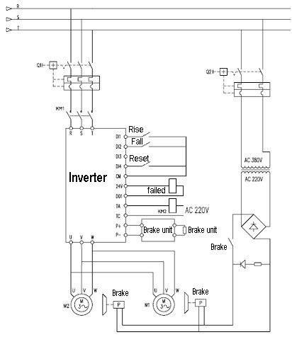
Figure 2 Main circuit of the construction hoist
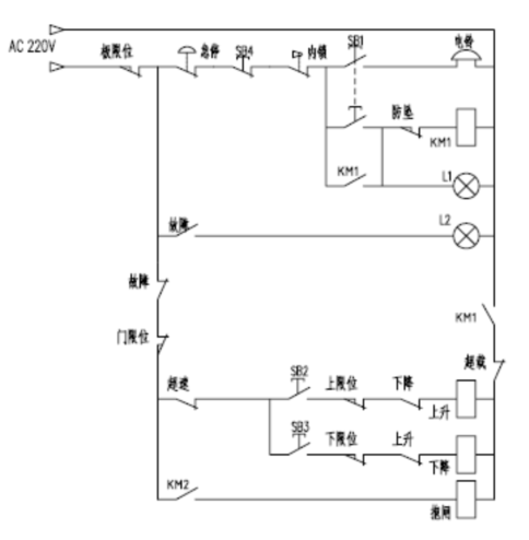
Figure 3 Control circuit of the construction hoist
4. System debugging of VVVF system of the lift
4.1 Debugging of VVVF system
When the circuit connection of the main circuit and the control circuit is correct, the system begins power-on debugging. The parameters of the motor are set through the operation panel on the inverter and the static self-learning mode is selected to identify the motor. After the identification is finished, the control mode, output frequency, acceleration and deceleration time, output mode of relay RO1, inspection frequency when brake releases and locks tightly, as well as other relevant parameters (the specific set of parameters is listed on each inverter manual) are set. After the completion of parameter settings, the no-load debugging, rated load debugging and 125% of rated load debugging are carried out according to the experimental rules for the construction hoist set by national standards. During the debugging process, if glide-hook phenomenon appears, the braking frequency can be properly increased, but it should not be too high, or the inverter will easily report failure. It is usually set within the range from 0.3 to 2Hz.
4.2 Security debugging of the lift
Security is the most important criteria in the construction hoist. In the system debugging process, safety tests must be carried out in accordance with the national standards. In the no-loading debugging process, limit switches such as the upper and lower limits of the lift, each gate of the suspension coop can be tested to see whether they are designed according to the design standards. After the commissioning of 125% of rated load, the overload protection is adjusted to 110% and overload test is carried out. In the anti-falling test, safety device is often installed in the construction hoist. Such device is an important component in the construction hoist, depended on which suspension coop would not fall. Drop test must be carried out once in every three months for the lifts used on the construction site, which could improve the output frequency of the inverter to see whether the safety will act or not when motor drives suspension coop to imitate the falling speed.
5. Conclusion
Debugged and tested on site, this design safely protects facilities and the test is convenient. When the lift starts and stops working, there is no obvious impact and declining phenomenon, accompanied with smooth speed regulation. The start torque is large at a low speed, which reduces impact on reducer and couplings, decreases impact on power grid, highly lowers the maintenance costs, improves work efficiency and yields remarkable energy saving effects. Thus VVVF system has good popularization and application value in the lift.
References
[1] GBT 10054-2005 construction hoist
[2] Practical Electrical and Technical Manual for Crane, Fu Deyuan, 2011
[3] Li Fangyuan. Application and Practice in Inverter Industry, 2006 (1)
Post time: Sep-14-2018